Packing
Die Form Rings
-
Style DF100 Braided 
Graf 
Graf 
Graf 
Braided 
Braided Top and Bottom with 45° Angle Cut -
Style DF200 Braided 
Graf 
Graf 
Graf 
Braided 
Braided Top and Bottom -
Style DF300 Braided 
Braided 
Braided 
Braided 
Braided 
Braided -
Style DF400 Graf 
Graf 
Graf 
Graf 
Graf 
Die Form -
Style DF500 Graf 
Graf 
Graf 
Graf 
Graf 
Die Form with 45° Angle Cut
Mechanical Packing
- Aramid Packings
- PTFE Packings
- Carbon and Graphite Hi-Temp Packings
- Synthetic Packings
- Flexible Graphite Ribbon Tape
- PTFE Joint Sealant
- Injectable Pump and Valve Sealant
- Flange Protectors
- Plastic
- Hardboard
- Plywood
- Pins and Washers
All technical advise and recommendation are rendered by Seller free of charge. While based on data believed to be reliable, seller assumes no responsibility.
| PTFE Stack Heights | |||
|---|---|---|---|
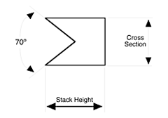
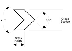
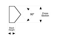
| Cross Section | Male Adapter | Vee Ring Max-Min | Female Stack Height |
| Plus .000” Minus .005” | Max-min Stack Height | Max-min Stack Height | Plus or Minus .005” |
| 0.125 | .050/.063 | .100/.083 | 0.125 |
| 0.156 | .062/.063 | .125/.083 | 0.156 |
| 0.187 | .075/.063 | .150/.083 | 0.187 |
| 0.218 | .087/.063 | .174/.083 | 0.218 |
| 0.250 | .100/.063 | .200/.083 | 0.250 |
| 0.281 | .112/.063 | .225/.083 | 0.281 |
| 0.312 | .125/.063 | .250/.140 | 0.312 |
| Plus .000” Minus .010” | Max-Min Stack Height | Max-Min Stack Height | Plus or Minus .010” |
| 0.343 | .137/.063 | .274/.140 | 0.343 |
| 0.375 | .150/.063 | .300/.156 | 0.375 |
| 0.406 | .162/.063 | .325/.156 | 0.406 |
| Plus .000” Minus .010” | Max-Min Stack Height | Max-Min Stack Height | Plus or Minus .010” |
| 0.437 | .175/.063 | .350/.197 | 0.437 |
| 0.468 | .187/.063 | .374/.197 | 0.468 |
| 0.500 | .200/.063 | .400/.197 | 0.500 |
| 0.531 | .212/.063 | .425/.197 | 0.531 |
| 0.562 | .225/.063 | .450/.197 | 0.562 |
| 0.593 | .237/.063 | .474/.197 | 0.593 |
| 0.625 | .250/.063 | .500/.250 | 0.625 |
| 0.656 | .262/.063 | .525/.250 | 0.656 |
| 0.687 | .275/.063 | .550/.250 | 0.687 |
| 0.718 | .287/.063 | .574/.297 | 0.718 |
| 0.750 | .300/.063 | .600/.297 | 0.750 |
-
PTFE Female Adapter 
-
PTFE Vee Ring 
-
PTFE Male Adapter 
-
Recommended number of V rings per set PSI No. of V rings 0-400 3 400-1800 5 1800-4500 6 4500 and up 7

Cup & Cone Sets
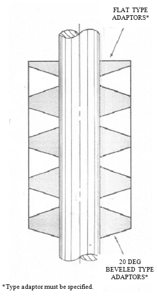
Cup and Cone packing of PTFE (Polytetrafluorothylene) seal with less pressures than similar “slug” packings.
The cup seals on the packing gland I.D., while the cone seals on the shaft O.D. The combination of the packing acts as a bearing when side thrusts are encountered.
Packing rings should not be cut or slit when installed. These cuts can form a leak and the packing will not seal. To properly install the cup and cone packing, it must be slipped over the end of the shaft.
When ordering cup and cone packing, the following dimensions are necessary:
- The shaft or rod O.D.
- The packing gland I.D.
- The effective stack height
